Wednesday, December 16, 2009

How to fire up an LS engine

These days you can buy an ignition system to transplant an LS engine into damn near anything. But, back when GMPP first put this carbureted crate engine package together, I had to outsource the fuel and ignition systems via the aftermarket. UMI Racing Products (http://www.umiracing.com/) was the first company I found that made a good and reliable system.


The UMI system mounts right to the back of the intake manifold where the distributor would reside on an old small block engine. The cool thing about the UMI arrangement is that not only will it fire the ignition, but it's also got built-in relays for running electric fans and it will cycle them on and off according to temperature settings that you can program via a laptop. You can also create your own timing map and if you're the type that doesn't like a rough idle, this ignition system will constantly vary the timing advance to settle down the rpm variation at idle. It's a pretty trick piece!

Aside from power and ground connections everything else just plugs in. The wiring harness plugs into the coil packs.


The crankshaft reluctor wheel sensor is tapped into via this plug. You'll need to tell UMI or whoever you get an ignition system from whether you have a gray or black plug. This denotes the number of teeth on the LS engine's relutctor wheel (24x or 58x)


The cam sensor is also plugged into:


the factory temperature sending unit is located in the cylinder head on the driver's side. This is also plugged into the ignition computer.


This micro switch is bolted to the carburetor flange and sends a signal to the computer to tell it when the throttle linkage is in the idle position.


And finally, a MAP sensor is plumbed into a vacuum at the base of the Road Demon 650 cfm carburetor to tell the computer to advance the timing as the vacuum level drops, which is when the hammer is down and the butterflies are wide open!


That's pretty much it. LS engines doen't have a provision for a mechanical fuel pump (except for some cool aftermarket LS engine blocks that are out there!) so we needed a fuel system.

BG Fuel System's BG280 fuel system (http://www.barrygrant.com/) features a 280 gph electric fuel pump, an BG 2-Port Plus adjustable fuel pressure regulator, and a BG000 reusable fuel filter. We plumbed all of this into a 650cfm Road Demon carburetor.


Next time, we'll drop the engine and trans into the chassis!

It Rolls! the '67 Chassis comes off the frame table and hits the garage floor

With the front and rear suspensions finished, we set the chassis on the ground for the first time with the wheels in place. Seeing the chassis off the table was major motivation to keep moving! Note that the new control arms aren't on the IFS yet. Mike wasn't done finished TIG welding them and I was in a rush to get the frame on the ground.


Fabbin' the engine mounts was a lot easier at ground level than up on the frame table.


Next, Mike Kim built a sheetmetal tranny mount. Pictured is Brian Busby a good friend who let me tie up the corner of his garage while we built the chassis.


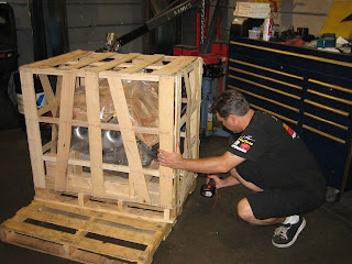
what's in here? Busby cracks open a crate.


it's 480hp of all-aluminum GM Performance Parts LS2 goodness! We couldn't resist the urge to put it in front of the firewall and make engine noises out loud.


Before we slammed the LS2 into the chassis we took it over to Westech Performance Group in Mira Loma, California, for a quick dyno-tuning session. Scott Urschel from UMI Racing was one of the first guys to build an igntion system to fire the coil-on-plug system of the LS engine and with a little tweaking and a new camshaft from Comp Cams, this puppy cranked out 480hp!


Next blog we'll find out how well the engine fits into the chassis and what it takes to make a carbureted LS2 run. stay tuned.

Chassis Building Part 5: IFS install

While in a normal installation Scott's IFS would provide plenty of suspension travel, our needs dictated some changes. In stock form the ball joints limited the a-arm travel to 9-inches. We ground some material away from the ball joint housing to increase its pivot angle and increase the travel of the front suspension:


This upper a-arm ball joint housings increased suspension travel to 12-inches locked out. But, I planned on tucking 22-inch wheels inside of the fenders, which meant that I needed at least 14-inches of travel to raise the truck up high enough for the tires to clear the fenders in order to make a u-turn.


The solution was a new pair of upper a-arms. The new arms used rod ends for the inner pivots and a spherical bearing for the outer pivot. Unlike the rear arms, we couldn't mount the sperical bearings vertically. This would have required us to build a different spindle mount. A uniball mounted horizontally won't give us any increase pivot angle unless we use a high-misalignment spacer inside of the bearing with a smaller diameter bolt. We once again used FK Bearing uniballs in our arms. The combo of Scott's spindles and lower arms with our upper arms resulted in over 15-inches of usable suspension travel.


Chassis Building Part 4: IFS from Scott's Hot Rods and Customs

The front suspension of the C10 required quite a bit less fabrication on our part. We used a Scott's Hot Rods IFS (http://www.scottshotrods.com/) as a base and then re-worked the upper arms for increased travel. The backbone of Scott's IFS is this custom crossmember:

This particular IFS is setup for coilovers. Ours would use Slam Specialties RE-7 airbags (http://www.slamspecialties.com/) for adjustability.

The IFS is built in a jig to ensure the track width is perfect.


Scott's doesn't just build suspensions:


In fact, the shop specializes in sheetmetal fabrication and has built many award-winning rides from scratch.


Now back to the garage!

Tuesday, December 8, 2009

Chassis Building Part 3

A lot of work went into the design of the IRS. The suspension was setup not only for maximum suspension travel, but also with some thought given to instant center, roll center, anti-dive, and all of those other cool terms for racecar handing traits. Here's a look at the mounting points for the upper A-arms:


Note that jamb nuts for the rod ends are not in place nor are the rod ends adjusted properly. Dont start sending hate mail about it, okay?


With the rear arms mocked up, we took the stock Expedition half shafts to the bandsaw and cut a four inch section out of each shaft. We then sleeved the shaft with chromoly tubing so that it could telescope as we cycled the suspension. This allowed us to verify our plunge figures, resulting in final measurements we'd use to have new shafts made from super-strong 300M material.


Here's a look at one of the upper A-arms. That piece of tubing on the right will eventually get cut off flush and capped.


how much travel do we get out of the IRS? Well, ride height is set with the arms level to the chassis and the chassis is 7-inches off the ground. With the axles in place, the suspension has 7-inches of up travel and 7-inches of down travel for a total of 14-inches. Nice!


Once we had the IRS mounted and the control arms built, we made a pair of sheetmetal mounts for a fuel cell. The aluminum fuel cell came from Brother's Truck Parts in Corona, California and is built for '67-'72 Chevy trucks.


At some point when I get brave, I'm gonna have to modify the fuel cell because it holds less than 12 gallons and I won't get out of the state with my lead foot controlling the throttle.


Chassis Building Part 2

The framerails were built from 20-foot long sections of 2x4x.120-wall rectangular steel tubing, which we cut into smaller pieces. Each section was miter-cut and MIG-welded together and then gussetted with a 3/16-inch thick steel plate.

once the backbone of the chassis was essentially put together, we focused on mocking up the Ford 8.8-inch IRS centersection and knuckles, and then crafting control arms to link the two parts together.


The control arms pivot on 1-inch diameter spherical bearings, commonly referred to as "uniballs". When mounted in a vertical position, the uniball gives the control arm a nearly limitless range of motion, unlike a common balljoint which locks up at about 20 degrees of angle.


There are several ways we could have mounted the center section for the IRS using tubular mounts. But, Mike Kim loves to TIG weld and he loves to use the dimple die tool even more so we decided to use laser-cut sheetmetal to build a front and rear bulkhead for our mounting points. Not only would this be a lighter way to mount the center section, but we also designed upper A-arm mounts into the bulkheads as well. And you have to admit they look pretty cool.